CSE 291 Final Report
Interactive Real-Time BRDF Editing under Environment Lighting
(Cristin) Ailie Fraser
March 20, 2015
Abstract |
Outline |
| The ability to interactively edit materials in a rendered scene is important for graphic artists and designers. Rather than adjusting the values of parameters for an analytic BRDF model, a more intuitive method would be to paint edits directly on the rendered image and interactively see results. When doing this, a number of questions arise. How can we constrain the user’s editing options to ensure the output is realistic, while still giving them flexibility with editing? What kinds of edits do users want to make, and how can we solve for a BRDF that matches these? This report will provide an overview of previous research in the areas of BRDF editing and interactive lighting design, show some examples of ways to make basic material edits, and discuss the challenges and possibilities for building an intuitive BRDF editing system. |
Introduction
The large-scale goal that inspired my project is to develop a method for artists to interactively edit the reflectance properties of rendered materials in an intuitive way. When graphic artists design a scene, one of the most important steps is defining how each object interacts with light. Since this has a direct effect on the appearance of the object, it is important for artists to have fine-grained control over the object's reflectance properties. These properties are represented as Bidirectional Reflectance Distribution Functions, or BRDFs.
In its simplest form, a BRDF is a four-dimensional function that describes the amount of light reflected given the incoming and outgoing directions (both of which are parameterized by the spherical coordinates \(\theta\) and \(\varphi\)). The BRDF is defined as the ratio of incident light from the incoming direction to exitant light in the outgoing direction [Marschner et al., 1999]. BRDFs can be higher dimensional when factors such as wavelength (colour) or spatial variation are included. BRDFs of real-world materials can be measured by capturing images of a material under all possible viewing and illumination directions. BRDFs can also be represented by analytic models designed to approximate real-world effects [Matusik et al., 2003].
Most existing methods for editing BRDFs involve setting the values of various parameters in a BRDF model. However, many BRDF models are represented by rather complicated equations, and the effect of changing a given parameter's value may not be intuitively clear to a novice, or even to an experienced graphic designer. In addition, when graphic artists design a scene, they tend to draw on objects directly, so being able to paint an object and have the reflectance update automatically would be more intuitive than setting parameter values manually.
The overall goal is therefore to develop an real-time interactive BRDF editing system that allows users to edit intuitive material properties by painting directly on the objects in a rendered scene. The scene should be lit by environment lighting, since this allows for much more realistic and natural-looking lighting than simple point source lights. The edits should also be made to the object under this environment lighting so that the artist is interacting with the material as it will appear in the final image, rather than in a constrained setting such as under a single point light source. Finally, the user should be given as much artistic freedom and flexibility as possible while still ensuring that the final product is photorealistic and can be represented by a BRDF.
Background
In this section I will discuss some of the previous work that has been done on interactive editing of lighting and BRDFs in a rendered scene, to provide some background that newer designs can draw from, and point out some of the areas that still need improvement.
Interactively Editing Lighting & Effects
A number of systems have been developed that allow users to interactively edit and manipulate the lighting in a scene. These include manipulating effects such as shadows and reflections, as well as changing the direction, intensity and colour of lights in the scene. While this is a different challenge than editing BRDFs, the design and interaction modalities of these systems can inform the design of BRDF editing systems, as both involve interacting with a rendered scene.
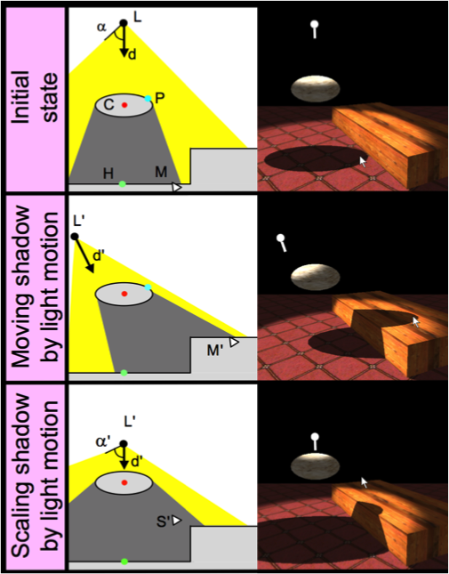
Pellacini et al. [2002] developed a system for interactive shadow editing in which users can move, rescale or rotate shadows by clicking on a shadow in the scene and dragging it (see image). The system then inversely computes the new light or object positions that will cause the edited shadow. In this system, only point light sources are used and the shadows are rendered using the technique of shadow mapping. The system stores a depth image from the point of view of each light source to determine what areas of the scene are not visible to that light source. When the user selects a point, the system finds the 3D position of that point using the camera’s depth buffer, then checks the shadow maps to see which light and which object are casting the selected shadow. Once this is determined, then as the user moves the mouse around, the system moves the light or object accordingly.
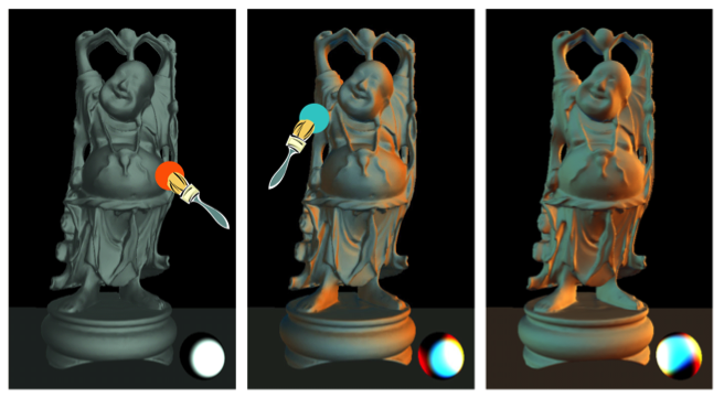
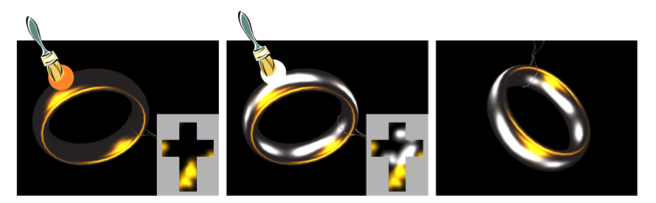
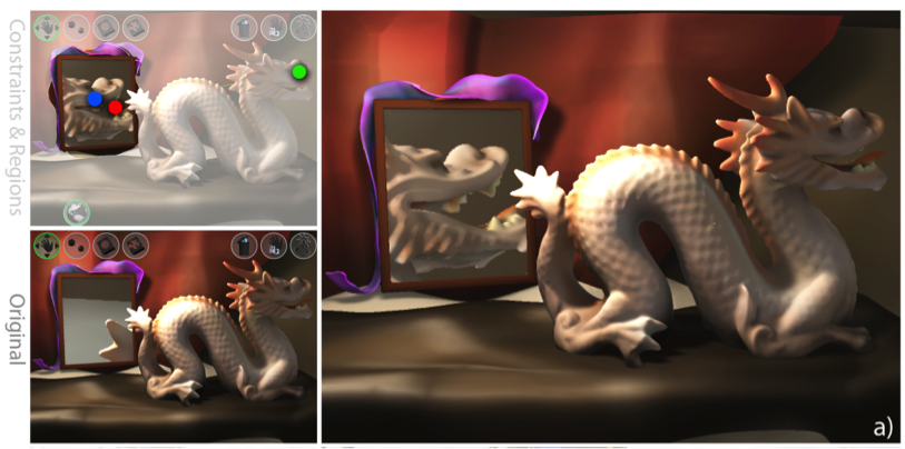
Okabe et al. [2007] developed a system called Illumination Brush, in which users can paint colours on an object, and the lighting is inversely calculated to create the painted appearance. In this system, the diffuse and specular components are edited separately. The user can either paint diffuse colours with the diffuse brush (see image), or can paint coloured specular highlights with the specular brush (see image). This system only creates synthetic low-frequency lights to cause these effects. A later system developed by Pellacini [2010] works in a similar way but allows for more realistic lighting effects as it uses environment map lighting. This system allows users to change the contrast, position, and blur of lighting effects and it updates the environment map to reflect the user's changes. To do this, the user first draws two strokes, one on the object they wish to edit and one on the background. The system then separates the image into foreground and background images, and also separates the environment map into the component that lights the foreground and the component that lights the background. Then, any subsequent edits to the image cause corresponding edits to the foreground environment map, leaving the background unchanged (see image).
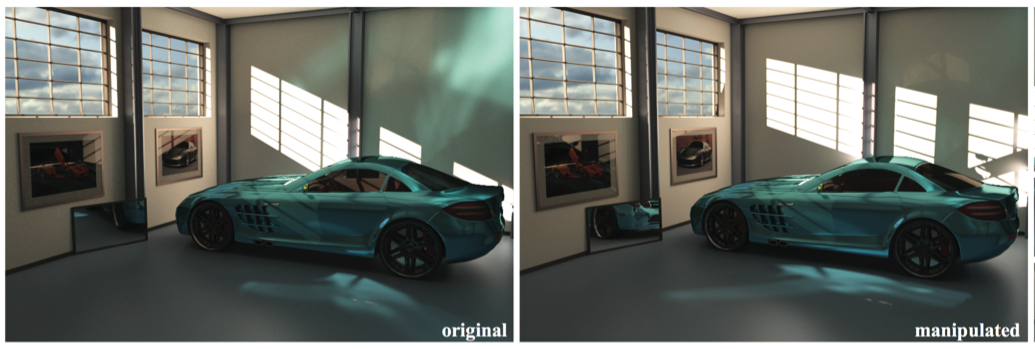
Systems have also been developed that allow for artistic non-realistic edits. For example, Kerr et al. [2010] built a system called BendyLights that allows users to curve light rays for artistic control of the illumination, by using a nonphysical lighting model. The system displays a tube showing the direction of travel of the point source light. The user can drag and rotate this tube, and can also deform it by clicking and dragging certain points along the tube (see image). This is used for artistic effects to make a scene look better, such as making a shadow smaller than it realistically should be. A later improvement to this system allows for interactive manipulation of more complex lighting effects such as caustics and reflections (see image) [Schmidt et al., 2013]. This system also displays the paths of light and allows the user to click and drag them. Finally, there is also a system for interactive editing of mirror reflections for artistic effects, in which the user can select what part of an object they wish to appear in a mirror, and the system redirects the mirror reflection direction in real-time to match this (see image) [Ritschel et al., 2009].
Interactive BRDF Editing
Editing BRDFs in real-time is more challenging than editing lighting, because the appearance of materials depends directly on the lighting, viewpoint, and object geometry, so generally one or multiple of these must be fixed to allow real-time changes [Ben-Artzi et al., 2006]. In addition, more detail is typically required for an object's BRDF than for lighting, since the object is directly visible on the screen, whereas the actual lights are not usually visible in the scene. All we see is the reflections of the lights off objects in the scene which do not require as much detail, especially for diffuse objects. There are several systems that have been developed that address these challenges and allow for real-time editing of object reflectance.
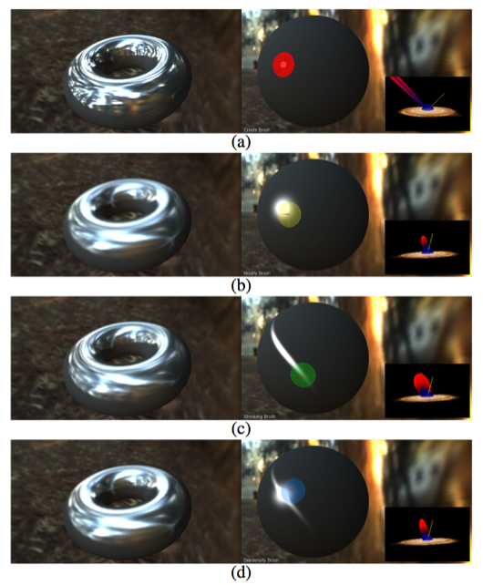
BRDF-Shop is a system developed by Colbert & Pattanaik [2006] in which users can interactively position and manipulate specular highlights. The interface displays the final object under environment lighting on the left, and a sphere under point source lighting on the right. The point source light is generated by using the brightest point in the environment map, thus providing a rough approximation to the environment lighting. The user interacts with the sphere and the changes are shown in real-time on both images (see image). The system uses the Ward Gaussian BRDF model because it has fairly intuitive parameters for defining and modifying specular lobes. There are four brush modes: create a highlight, edit roughness, add streaking (for anisotropy), and intensify/de-intensify. To update the scene on the left in real-time, the environment map has been prefiltered and integrated over using quasirandom importance sampling that runs on the GPU. While this is a very good example of an interactive BRDF editing interface, there are still some things to be desired. The range of options for editing are somewhat limited, since the user can only edit specular highlights, and not other spatially varying properties. This is mainly due to the nature of the BRDF model chosen. Ideally one should be able to use any BRDF model, not only one that happens to have intuitive parameters. Also, the user must paint on the sphere, which for editing only highlights can be helpful since it isolates one highlight, but it does not allow the user to interact directly with the final object.
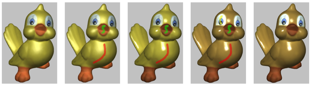
Pellacini & Lawrence have created an interactive system called AppWand [2007]. In this system, the user first draws a few strokes on the object to indicate what region to edit. Then, they select what kind of edit to make to this region by setting the parameters for the chosen BRDF model. This system can take in any BRDF model. These changes are then smoothly propagated spatially to the rest of the object, so similar edits get applied to other regions with similar appearance (see image). Materials are represented as a collection of BRDF samples for different points on the surface. To find regions with similar appearance, the system computes the distance between samples which the authors define as "the average squared difference of their values weighted by the cosine term, integrated over incoming and outgoing directions" [Pellacini & Lawrence, 2007]. While this system allows the user to draw directly on the object, this is only to specify the area of interest. The actual edits are done by specifying new parameter values for the BRDF, which for many BRDFs are not intuitive and thus it can require some trial and error to reach the desired appearance. In addition, this system is mainly intended for global edits, and making small local changes is not as straightforward.
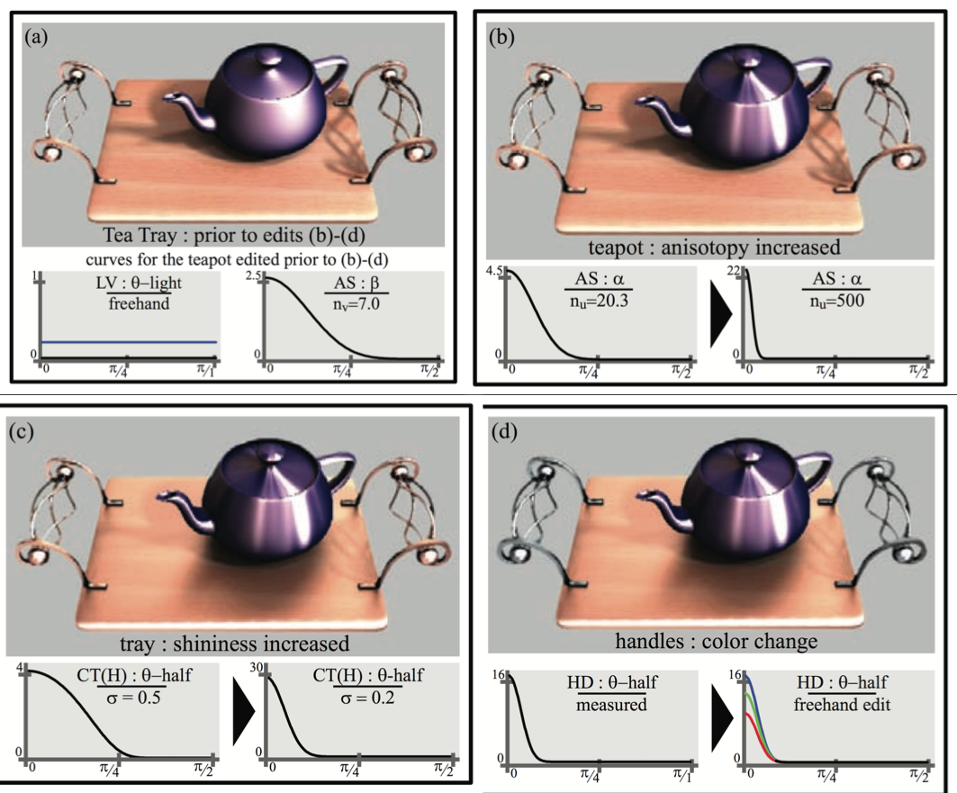
Ben-Artzi et al. have developed a system for real-time BRDF editing under complex illumination [2006]. Here, they are able to represent any BRDF (parametric or measured) by writing it as a linear combination of basis functions. The BRDF parameters are then displayed as curves that the user can manipulate to change their values. The image of the object updates in real-time to reflect these changes (see image). By parameterizing the BRDF in a meaningful way, the system can provide somewhat intuitive curves. However, the user is not able to paint directly on the object, so the process may still require trial-and-error to get the effects the user desires.
An important question related to editing BRDFs is how to represent BRDFs in an intuitive way, and how to allow for any arbitrary BRDFs. As the previous example discusses, parametric BRDFs can often be factored using physically meaningful parameters, but what about BRDFs measured from real-world objects? Since these are represented as a discrete collection of measurements, there is no immediate way to edit them or represent them intuitively. One solution is to approximate them using a parametric model by solving for the parameters that most closely match the measurements. Another solution proposed by Matusik [2003] is to treat a measured BRDF as a high-dimensional vector. This allows for the creation of new realistic BRDFs by interpolating and extrapolating from a collection of measured BRDFs. Matusik does this by defining a set of descriptive parameters such as "shiny", and "plastic", and then classifying a set of measured BRDFs by noting whether they belong to each category or not. He then derives a "trait vector" for each category based on the distribution of samples and their ratings in each category. Then to increase or decrease a trait given a BRDF, one can add or subtract the trait vector from the BRDF's vector. This provides a way to intuitively edit BRDFs from measured data.
Implementation
For my project, I built an interface that displays a sphere rendered under environment lighting, and allows the user to make simple spatially varying changes to the sphere's BRDF. Here I will discuss the details of this implementation.
Environment Mapping
Real-time rendering under environment lighting can be a slow process, because it involves integrating over the entire environment map for each point in the scene. To allow for real-time display, I chose to pre-render a collection of images of the sphere with different values for the BRDF parameters, and combine these at runtime. The pre-rendering process could be sped up by incorporating techniques such as spherical harmonic prefiltering as done in [Ramamoorthi & Hanrahan, 2002].
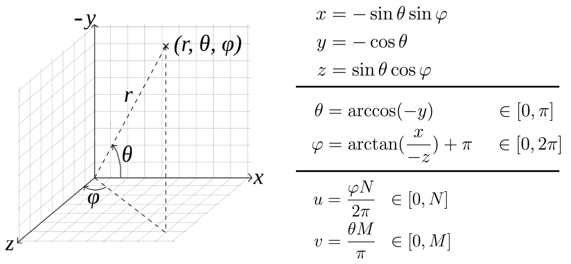
Figure 1. Converting to spherical coordinates. The direction is given by the 3D vector \((x, y, z)\). Assuming \((x, y, z)\) is a unit vector, the radius \(r\) is therefore 1. \((u, v)\) is the pixel location of the direction given by \((\varphi, \theta)\) where the environment map is N pixels by M pixels in size.
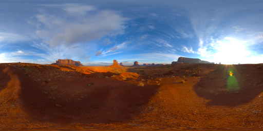
I will now discuss the details of my implementation for rendering a sphere under environment lighting. I chose to use the latitude-longitude format for environment maps, because it is straightforward to index into. Points on the environment map are indexed by the spherical coordinates \(\theta\) and \(\varphi\), so finding the light intensity in a given direction is simply a matter of converting the direction into spherical coordinates and looking up the corresponding point in the environment map. Figure 1 shows the formulas for converting to and from spherical coordinates.
I started by rendering a perfect mirror sphere under environment lighting (Figure 2). To do this, we simply calculate the direction of perfect mirror reflection at each point on the sphere, and shade that point with the intensity value at the corresponding point in the environment map. The direction of perfect reflection is given by \( \vec{m} = -\vec{s} + (2\vec{s} \cdot \vec{n})\vec{n} \) where \(\vec{s}\) is the viewing direction and \(\vec{n}\) is the surface normal.
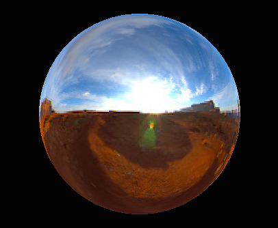
Figure 2. Rendering of a perfect mirror sphere under this environment map.
BRDF Models
To calculate the BRDFs, I calculate and pre-render the diffuse and specular components separately, and add them together at runtime. The diffuse component is defined as simply \(\rho(\vec{\omega}_{i}, \vec{\omega}_{o}) = k_{d}\), where \(k_{d}\) is the diffuse coefficient, a value between 0 and 1 (or three values, one for each RGB channel).
For the specular component, I implemented both the specular Phong BRDF, and the Torrance-Sparrow BRDF. The specular Phong BRDF is defined as: \[\rho(\vec{\omega}_{i}, \vec{\omega}_{o}) = (\frac{1 + \sigma}{2\pi}) \cdot k_{s} \cdot \frac{\max(0, \vec{\omega}_{o} \cdot \vec{m})^{\sigma}}{\vec{\omega}_{i}\cdot \vec{n}}\] where \((\frac{1 + \sigma}{2\pi})\) is a normalization term as described in [Ramamoorthi & Hanrahan, 2001], \(k_{s}\) is the specular coefficient and \(\sigma\) is the specular exponent. As an alternative option, I implemented a simplified Torrance-Sparrow microfacet BRDF model, as described in [Ramamoorthi & Hanrahan, 2001]: \[\rho(\theta_{i}, \theta_{o}) = k_{s} \frac{S}{4\cos{\theta_{i}}\cos{\theta_{o}}} \;\;\;\;\;\;, \;\;\;\;\;\; S = \frac{1}{\pi\sigma^{2}} e^{-(\frac{\theta_{h}}{\sigma})^{2}}\] where \(\theta_{h}\) is the half angle between \(\theta_{i}\) and \(\theta_{o}\). In both the Phong and Torrance-Sparrow models, \(k_{s}\) represents the overall specular intensity, and \(\sigma\) controls the roughness or shininess of the specular lobe. I compared the results of my specular Phong renderings to those from Prof. Ramamoorthi’s spherical harmonic prefiltering code to verify my method, and though there is a slight difference in overall brightness, they otherwise match. My program can load both HDR and LDR lat-long environment maps, and for an environment map size of 300x300 and a final image size of 320x240, each image takes approximately 6 minutes to render on my laptop. I pre-rendered a series of images with varying specular exponent values for both Phong and Torrance-Sparrow models, and varying RGB intensity values for the diffuse BRDF.
Editing Interface
I built an interface in MATLAB for editing (Figure 3). This interface shows the sphere under environment lighting (left) and point source lighting (right).
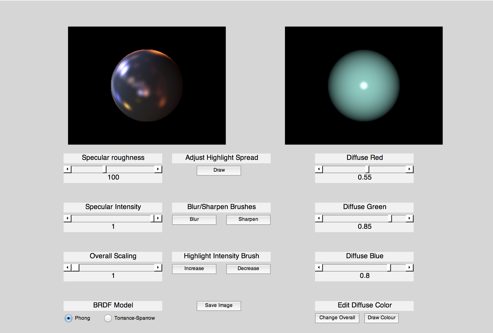
Figure 3. My editing interface.
As a preliminary step and control case, I first implemented sliders to globally control the values of the parameters \(k_{d}, k_{s}\) and \(\sigma\). For the diffuse coefficient, the user can set separate R, G and B values to set the diffuse colour. There is also a slider to set an overall scaling factor, and at the bottom left the user can select the BRDF model being used for the specular component. See Figure 4 for a video of these edits being made.
To allow for interactive spatially varying changes, I then implemented several brush options. First I created a diffuse brush that allows the user to select a colour, and draw that colour directly onto the sphere. After selecting a colour, the user makes a brush stroke on the image, and the diffuse coefficient for the pixels in the surrounding area (within a radius of 25 pixels) is updated to be the chosen colour. To make this look smooth, I added an approximate Gaussian falloff with standard deviation 15. See Figure 5 for a video of the diffuse brush being used.
I then created brushes to edit the specular intensity and roughness. The roughness brushes are labeled as "blur" and "sharpen", since these are intuitive brush names and are familiar from programs such as Photoshop. As in the diffuse case, the user selects a brush and then draws a stroke on the image. The surrounding area is then updated to a higher or lower value of \(k_{d}\) (for intensity) or \(\sigma\) (for roughness), depending on whether the user has chosen to increase or decrease the value. Note that with the Phong model, increasing \(\sigma\) increases the sharpness of the highlights, whereas with the Torrance-Sparrow model, increasing \(\sigma\) decreases the sharpness. See Figure 6 for a video of the specular brushes being used.
For each of the parameter values \(k_{d}, k_{s}\) and \(\sigma\), I store a texture map that holds the value of the parameter at each pixel in the image. Then, to display the final image, for each pixel I look up the intensity of the pre-rendered image with the corresponding parameter value at that pixel. So, when a brush stroke is made, the texture map for the selected parameter is updated at the pixels surrounding the brush stroke. This is similar to the technique used by [Ben-Artzi et al., 2006] for spatial variation.
My pre-rendering program was written in C++, and my interface was written in MATLAB. The code for both can be downloaded below, in the Resources section.
Discussion
Though my interface provides relatively simple options, these concepts could extend to more interesting cases, such as editing objects other than spheres (where having spatial variation would make more sense), using more complex BRDF models, and having more brush options to create a wider range of effects. I will now discuss some of the challenges that these extensions would present, and then propose a collection of editing options that would be feasible for an interactive editing system while allowing the artist freedom and flexibility.
One big tradeoff when designing such a system is this: If we let the user have full artistic freedom and paint whatever they want on the object, we can’t guarantee this will be photorealistic or even close to photorealistic. However, if we constrain the user's editing options too much, they may not be able to make the edits they want to make. One possible solution is to let the user paint anything on the object, and then look for the “closest match” among the prerendered images, or solve for the best fitting parameters, to fit what the user has drawn. However, with a complex BRDF this may be a difficult or slow search, and with a simple BRDF such as Phong the range of possible images is more limited, so the chances that the closest match actually looks like what the user drew may be quite small. For example, in my interface, the simple Phong and Torrance-Sparrow models do not allow for anisotropic effects such as streaking highlights, so if I were to draw these on the image, the resulting closest match would not be very close to what I drew.
So, assuming the user should not have complete freedom to paint on the object, the question then becomes: what editing options should they have? For example, in my interface I had a blur and sharpen brush, which can be very useful. What else might the user want to edit and how can we represent this with any BRDF?
Future Steps
To address the first part of this question, I will now propose a collection of basic editing modes than an interface should have, and provide a series of images to illustrate the changes that could come out of this. These are based on previous papers discussed here as well as my experimenting with the interface I built. However, it should be noted that since user interface design is a Human-Computer Interaction problem, having one person make an executive decision regarding what users want is rarely the right move. After my proposal below, I will discuss an alternative solution to this.
Proposed editing options:
- Edit diffuse colour
- Edit specular intensity and colour
- Sharpen / Blur highlights
- Stretch highlights
- Increase or decrease metallic-ness. In other words, change the distribution of energy between specular and diffuse. This is what the intensify brush does in [Colbert & Pattanaik, 2006].
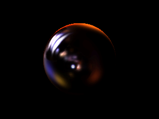
Below is an example sequence of edits to illustrate the freedom that such a system would allow.
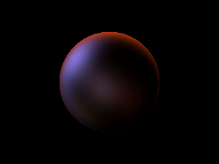
Step 1. Initial image.
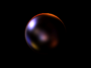
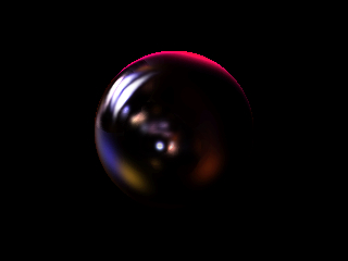
Step 2. Decrease overall specular roughness (increase sharpness). This was done in my interface.
Step 3. Increase sharpness in certain areas only using sharpness brush. This was done in my interface.
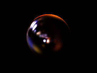
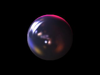
Step 4. Decrease specular intensity for the highlights in the middle using the specular intensity brush. This was done in my interface.
Step 5. Stretch highlights using brush to create anisotropic streaking effects. This was done in Photoshop.
Step 6. Change the colour of specular highlights using a brush. This was done in Photoshop.
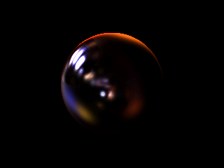
Step 7. Set overall diffuse colour. This was done in my interface.
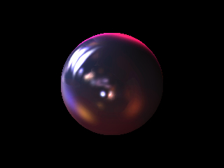
Step 8. Change diffuse colour in certain areas using diffuse editing brush. This was done in my interface.

Step 9. Decrease overall specular intensity. This was done in my interface.
As mentioned above, a common problem with interfaces and programs is the fact that one person made the decisions regarding what interactions should be allowed, and so the system ends up being less flexible and accommodating of others' needs than it should be. Therefore, what one should really do when developing a system like this is conduct a user study or a crowdsourcing study to determine the best brushes or best parameters that people want to edit, as well as what each one should be called. I propose that first, a small user study should be conducted by observing the workflow of a small number of graphic designers to see what kind of operations they do. As well as being observed, they should be interviewed to see what kind of operations they generally need to do, and find out what difficulties they may have with their current methods. Based on these results, several prototypes should be implemented that allow different amounts of freedom for making these edits. These prototypes should be tested with a larger group of users that includes novices, and the resulting images should then be scored by independent raters. The users could also fill out a survey after testing the prototype to determine what they found useful and what they found challenging. Based on the results from these, another iteration of prototypes should be created and tested and this process repeated until the results are satisfactory.
Finally, the question remains as to how to build a system that allows for arbitrary BRDFs, both measured and parametric. One possibility could be to use ideas similar to those in [Matusik, 2003], namely to classify a large collection of BRDFs based on intuitive parameters or categories, and then interpolate between them. One could crowdsource this process by asking crowd workers to describe various rendered materials using descriptive words based on the editing operations determined in the user study discussed in the previous paragraph. Based on these classifications, one could then interpolate between given BRDFs when the user paints edits on the material.
References
Ben-Artzi, A., Overbeck, R., & Ramamoorthi, R. (2006). Real-time BRDF Editing in Complex Lighting. In ACM SIGGRAPH 2006 Papers (pp. 945–954). New York, NY, USA: ACM. http://doi.org/10.1145/1179352.1141979
Colbert, M., & Pattanaik, S. (2006). BRDF-Shop: An artistic tool for creating physically correct BRDFs. IEEE Computer Graphics and Applications, 26(1), 30–36.
Kerr, W. B., Pellacini, F., & Denning, J. D. (2010). BendyLights: Artistic Control of Direct Illumination by Curving Light Rays. Computer Graphics Forum, 29(4), 1451–1459. http://doi.org/10.1111/j.1467-8659.2010.01742.x
Marschner, S. R., Westin, S. H., Lafortune, E. P. F., Torrance, K. E., & Greenberg, D. P. (1999). Image-based BRDF Measurement Including Human Skin. In Proceedings of the 10th Eurographics Conference on Rendering (pp. 131–144). Aire-la-Ville, Switzerland, Switzerland: Eurographics Association. http://doi.org/10.2312/EGWR/EGWR99/131-144
Matusik, W., Pfister, H., Brand, M., & McMillan, L. (2003). A data-driven reflectance model. ACM Transactions on Graphics, 22(3), 759. http://doi.org/10.1145/882262.882343
Okabe, M., Matsushita, Y., Shen, L., & Igarashi, T. (2007). Illumination brush: Interactive design of all-frequency lighting. In Proc. Pacific Conference on Computer Graphics and Applications, IEEE Computer Society (pp. 171–180).
Pellacini, F., Tole, P., & Greenberg, D. P. (2002). A user interface for interactive cinematic shadow design. ACM Transactions on Graphics, 21(3). http://doi.org/10.1145/566654.566617
Pellacini, F., & Lawrence, J. (2007). AppWand: Editing Measured Materials Using Appearance-driven Optimization. In ACM SIGGRAPH 2007 Papers. New York, NY, USA: ACM. http://doi.org/10.1145/1275808.1276444
Pellacini, F. (2010). envyLight: an interface for editing natural illumination (p. 1). ACM Press. http://doi.org/10.1145/1833349.1778771
Ramamoorthi, R., & Hanrahan, P. (2001). A Signal-processing Framework for Inverse Rendering. In Proceedings of the 28th Annual Conference on Computer Graphics and Interactive Techniques (pp. 117–128). New York, NY, USA: ACM. http://doi.org/10.1145/383259.383271
Ramamoorthi, R., & Hanrahan, P. (2002). Frequency Space Environment Map Rendering. In Proceedings of the 29th Annual Conference on Computer Graphics and Interactive Techniques (pp. 517–526). New York, NY, USA: ACM. http://doi.org/10.1145/566570.566611
Ritschel, T., Okabe, M., Thormahlen, T., & Seidel, H.-P. (2009). Interactive reflection editing. ACM Transactions on Graphics, 28(5), 1. http://doi.org/10.1145/1618452.1618475
Schmidt, T.-W., Novak, J., Meng, J., Kaplanyan, A. S., Reiner, T., Nowrouzezahrai, D., & Dachsbacher, C. (2013). Path-space manipulation of physically-based light transport. ACM Transactions on Graphics, 32(4), 1. http://doi.org/10.1145/2461912.2461980
Resources
- Pre-rendering code
- Interface code
- Slides from March 6th Pixel Cafe talk
- Slides from final presentation in CSE 291 (essentially a shortened version of Pixel Cafe talk, with some additions to the end)